Field Diesel Units are effective in areas where there is a ready supply of Crude Oil but limited supply of diesel or fuel oil, such as remote oil fields or drilling locations. A Field Diesel Unit can fulfill fuel requirements for power generation and drilling operation. This unit extracts the Diesel component from the Crude Oil and then blends rest of the products back to Crude Oil stream. The Field Diesel Unit is supplied in easily transportable skids; it is quick to install and self-sufficient. The unit can be started when needed and stopped when the tanks are full. The Diesel produced by these units largely depends on the type of Crude Oil, the lighter varieties will provide greater diesel yield and higher cetane number.
Standard Sizes
- 200 BPD Crude Oil throughput
- 500 BPD
- 1,000 BPD
Major Units
- Desalter
- Fired Heater / Hot Oil Heater
- Distillation Column
- Diesel Stripper Column
- Instrument Packages
- Utility and Control Packages

Process
Preheating and Desalting
Crude Oil from storage is pumped through preheat exchangers to an electrostatic desalter and washed using pre-heated fresh water. The desalted crude is further heated in shell and tube exchangers with hot product streams before it enters the heater.
Heating
The preheated crude oil from desalter is then piped to the fired heater which is fueled by off-gas or one of the product streams. Crude Oil enters the heater’s convection section, passes through the radiant section, and exits the heater at suitable temperature for fractionation.
Distillation
The heated Crude oil from is flashed into vapor and liquid fractions in the flash zone of the distillation column. The vapor fraction rises through the wash zone fractionating trays of the column, whereas liquid fraction flows down to bottom through stripping section. At pre-determined operating temperatures, diesel fraction in the vapor condenses and flows back into liquid phase and is drawn as product from the chimney trays under level control into a diesel stripper. The specified diesel product is then cooled and supplied to product storage.
The lighter fractions go up and condense in an overhead air-cooled condenser. Part of condensate is fed back as reflux and the balance is blended with the residue from the Column bottom and mixed with the Crude Oil stock. The uncondensed gases are vented to Flare system or supplied to the fired heater.
A Crude Oil Topping Unit is a simplified refinery and allows for distillation of crude into Naphtha, straight run kerosene, diesel, and atmospheric residue (fuel oil). Pyramid E&C has complete value chain for design, supply, and commissioning of Topping units complete with auxiliary and utility packages. The modular construction of topping unit is preferred for reducing site work and achieving fast track projects.
Standard Sizes
- 2,000 BPD
- 5,000 BPD
- 10,000 BPD
Major Equipment
- Desalter
- Fired Heater
- Distillation Column
- Side Stripper Columns
- Instrument Packages
- Utility and Control Packages

Process
Preheating and Desalting
Crude Oil from storage is pumped through preheat exchangers to an electrostatic desalter and washed using pre-heated fresh water. The desalted crude is further heated in shell and tube exchangers with hot product streams before it enters the heater.
Heating
The preheated crude oil from desalter is then piped to the fired heater which is fueled by off-gas or one of the product streams. Crude Oil enters the heater’s convection section, passes through the radiant section, and exits the heater at suitable temperature for fractionation.
Distillation
The heated Crude oil from is flashed into vapor and liquid fractions in the flash zone of the distillation column. The vapor fraction rises through the wash zone fractionating trays of the column, whereas liquid fraction flows down to bottom through stripping section. At pre-determined operating temperatures, diesel fraction in the vapor condenses and flows back into liquid phase and is drawn as product from the chimney trays under level control into a diesel stripper. The kerosene product is extracted in a similar manner. The fractionated and stabilized products are then cooled and supplied to product storage tanks.
The lighter fractions go up and condense in an overhead air-cooled condenser. Part of condensate is fed back as reflux and the balance is blended with the residue from the Column bottom and mixed with the Crude Oil stock. The uncondensed gases are vented to Flare system or supplied to the fired heater.
Pyramid E&C offers standard as well as custom-built modular design for conventional as well as modular Hydroskimming refineries.
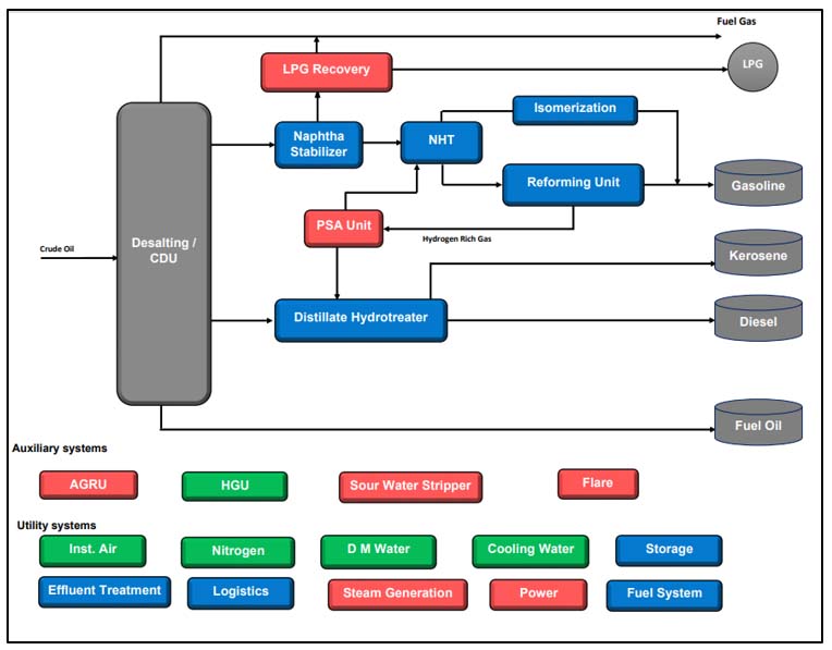
A Hydroskimming refinery contains an atmospheric distillation unit with a naphtha processing complex to produce gasoline from straight run naphtha and a distillate hydrotreater to produce low sulfur kerosene and diesel. Pyramid E&C seamlessly integrates the open art and licensed process and supplies the units on a single point basis. The units are modularized to the extent possible for ease of installation at site.
Standard Sizes
- 10,000 BPD
- 25,000 BPD
Major Units
- Atmospheric Distillation
- Naphtha Stabilizer
- Naphtha Hydrotreater
- Naphtha Reformer
- Isomerization Unit
- Distillate Hydrotreater
- Hydrogen Purification / Generation
- Sour Water Stripper
- Sulfur Recovery
Process
Distillation
The topping unit is first unit in hydroskimming refinery which produces straight run naphtha, kerosene, gas oil, and residue. The straight run products are stabilized and fed to downstream treatment units.
LPG Recovery
The naphtha fraction is stabilized in a column to reduce C3 and C4 content in naphtha. The LPG fraction from overhead condenser of the stabilizer is mixed with LPG from the reformer and sent to a de-propanizer. Stabilized naphtha is sent to the hydrotreatment unit. The overhead vapors of the LPG plant are then sent to the sweetening unit to be treated and used as refinery fuel gas in fired heaters.
Naphtha Hydrotreatment
Stabilized full range naphtha undergoes further processing in the Naphtha Hydrotreater to remove sulfur, nitrogen, and other impurities that would otherwise poison the catalyst used in the downstream catalytic reforming process. Sulfur removal is also required to meet gasoline sulfur standards. At this point the naphtha is split into heavy and light naphtha fractions specific octane boosting processes.
Reforming
Heavy naphtha is converted in the catalytic reformer into a stream comprising of aromatic components with an octane number higher than straight run naphtha. Expected octane number of the reformate typically varies in the range of 90 to 100. The reforming unit also generates a hydrogen-rich gas stream, as well as fuel gas and LPG fractions.
Isomerization Unit
Light naphtha from the Naphtha Hydrotreater is fed to the isomerization unit with hydrogen rich gas from reformer unit. Low octane naphtha is converted to high octane isomerate, stored into isomerate storage tank, and further sent to gasoline pool for blending
Hydrogen Purification
The hydrogen-rich gas from reformer is separated in a pressure swing adsorption (PSA) unit that recovers purified hydrogen suitable to feed the hydrotreating process. The PSA will typically deliver hydrogen with a purity higher than 95 mol%. Off-gas from the PSA unit is used as sweep gas for the flare system.
Distillate Hydrotreating
The intermediate distillates are combined, mixed with recycled hydrogen and then brought to the reaction temperature by a heater prior to being fed to the Diesel Hydrotreater. Off-gases from the stripper are routed to the acid gas removal unit before being sent to the fuel gas system for distribution to fuel gas users. Stripped liquids are heated and fed to a splitter column to be separated into kerosene and diesel and then routed to Jet Fuel and/ or USLD blending and storage as seasonal and market conditions.
- 25,000 BPD
- 50,000 BPD
- Atmospheric Distillation
- Vacuum Distillation
- Reformer / Isomerizer
- Distillate Hydrotreater
- Hydrocracker and / or Fluid Catalytic Cracker
- Coker or Visbreaker

Process
Vacuum Distillation (VDU) The atmospheric residue is processed in a vacuum tower to separate the gasoil and residue. Preheating sections of CDU and VDU are fully integrated in order to maximize heat recovery and minimize fuel consumption. From the vacuum tower overhead and vent gases are routed to a fired heater while the steam condensate is sent to the Sour Water Stripper. The vacuum gasoil stream (VGO) is sent to hydrocracking unit, distillate hydrotreater unit or light crude storage. Hydrocracking (HYK) The vacuum gas oil from the VDU is fed to hydrocracking unit for conversion into lighter products LPG, reformer grade Naphtha, Ultra-low Sulfur Kerosene (ULSK) and Ultra-Low Sulfur Diesel (ULSD). The hydrocracking process occurs in presence of a catalyst in a hydrogen rich environment at elevated temperatures and pressures. In this process, the high-boiling, high molecular weight hydrocarbons are cracked into lower-boiling, lower molecular weight hydrocarbons while sulfur and nitrogen present in the hydrocracking feed are removed. Fluid Catalytic Cracking (FCC) The vacuum gas oil from the VDU is fed to fluid catalytic cracking unit to maximize gasoline production. In the FCC, a fluidized bed of catalyst particles is brought into contact with the feed along with steam injection for stripping out hydrocarbon vapors associated with catalyst. The Alkylation unit is used to convert light olefins produced by an FCC or Coking unit into a gasoline blending component called alkylate.The Alkylation unit is considered only when the FCC unit has been selected for bottoms upgradation.
Visbreaking
The vacuum gas oil from the VDU is fed to the visbreaker, which thermally cracks large hydrocarbon molecules into naphtha, gasoline and residue by heating in a furnace. The cracked products are quenched with gas oil and flashed into a fractionator to separate light and heavy streams.
Coker
The residual product from the VDU is fed to the coking unit at high temperature and low pressure. Coking is a thermal cracking process used to convert low value residual fuel oil to higher-value gas oil and petroleum coke. The residue is fed to the bottom of fractionator where light ends are stripped to the maximum extent.
Pyramid E&C offers Bitumen Production refineries complete with auxiliary and utility units to monetize heavy crude oil. The flexible design allows production of different grades of bitumen.
Standard Sizes
- 5,000 BPD Crude Oil throughput
- 10,000 BPD
Major Units
- Atmospheric Distillation
- Vacuum Distillation
- Bitumen Blowing Unit
- Distillate Hydroeater
- Sour Water Stripper
- Sulfur Recovery
- Hydrogen Purification

Process
Vacuum Distillation
The atmospheric residue from atmospheric distillation unit is processed in a vacuum tower to separate the gasoil and residue. The residue drawn should be suitable for desired commercial grade of bitumen. Preheating sections of CDU and VDU are fully integrated in order to maximize heat recovery and minimize fuel consumption. Steam is used to strip vacuum residue at the vacuum tower bottom to ensure that the bitumen properties meet commercial grades.
Bitumen Blowing Unit
This unit uses air blowing to produce desired grade and quality of bitumen. The vacuum residue is charged to the unit using gear pumps through charge heaters. The feed residue is contacted with air steam mixture using sparger. A suitable temperature is maintained by controlling steam and air injection rates. The off gases from top are either flared or incinerated and converted bitumen is poured into the drum and left for cooling.
Auxiliary and Utility Systems
The auxiliary units required are sour water stripper, flare, effluent treatment unit, fire protection and fire & gas detection systems for normal operation of bitumen refinery. Major utility systems required are instrument and plant air, steam, power and process water.
Pyramid E&C has experience of Basic Design, Detailed Engineering, Procurement and Construction management for modular carbon black plants of capacities in multiples of 40 TPD. Pyramid E&C can also engineer and supply process units, offsite and utilities required for Tread, Carcass and Specialty Black Plants.
The basic process consists of atomizing the Carbon Black Feed Stock (CBFS) or Fuel Oil of suitable properties in the combustion zone of a reactor. The combustion of feedstock instantly vaporizes the feedstock and decomposes into primary carbon black and hydrogen. The remaining feedstock reacts with excess oxygen in the primary combustion stream to maintain the reaction temperature for carbon formation.
The hot, heavy carbon black smoke from the reactors enters the air preheater where thermal energy is transferred to preheat the primary combustion air. The reaction products are quenched rapidly with water sprays in quench tower.
From the air preheater the lowering of temperature in a tower from which then enters the bag filter that separates the fluffy carbon black product from the off gases. Carbon black particles are deposited outside the bag-filter and hot process gases filters off for utilization as fuel for specially designed boiler system to generate high pressure steam and in a specially designed dryer combustor furnace to supply energy requirement in pelletizing and drying section. The quantum of high-pressure steam which is generated through burning of these off gases meet the plant requirement of steam and power.
The fluffy density carbon black is then conveyed to the wet pelletizers where water is added to transform the product into wet granules. Dry palletization in rotating drums is also practiced for certain applications. The wet pellets are then dried in a rotary dryer where finished product goes to storage silos.
Major equipment

Handling
All the raw materials and finished products are handled as per the standard practice in the closed systems. Finished product handling is in closed system. The finished product will be stored in silos.
3D Model Snapshot

Storage
The unit has adequate storage facilities for all the raw materials and finished products. Carbon black feedstock received from refineries and molasses received from sugar industries are unloaded into isolated storage area in fixed roof tanks. Feedstock and Molasses are stored at an average temperature of 50°C through external steam heating. Additives are stored in raw materials godown. Steam generation is carried from waste heat in inline boilers and tail gas fired boilers. The excess steam will be utilized in captive power plant.
Completed Plant at BKT, Gujarat, India, Nov. 2019